My version of the Arduino-based Turntable Tacho

“This is based on a diyAudio project, with some little tweaks of my own.”
There is a thread over on diyAudio that’s a few years old but still very popular. Some folks figured out how to use an Arduino Uno with a sensor to accurately measure the rotational speed of a Turntable.
Maybe if you’ve got a modern TT or a model renown for rock-solid speed and low wow & flutter then this is of no interest. But some of us have, well, older machines.
It’s really very simple – the hard work (the software or ‘sketch’) has been done for you, and it’s basically about connecting power to the Arduino, wiring up the sensor and positioning it.
You may not be surprised that I’ve built a few iterations of these for a couple of reasons!
First, my Linn Sondek LP12 is over 30 years old and is belt-driven, with an AC motor and a (reasonably) simple power supply driving the motor. (known as the ‘Valhalla’ power supply – essentially an AC regenerator). The rotational speed is adjustable – by mechanically orientating the motor spindle off the vertical by lighting or loosening a couple of retaining screws (!). Second, I’m part-way through (!) building another diyAudio project – a multi-phase sine-wave generator that has much more flexibility than the Valhalla (including voltage supply and phase offset), but which doesn’t have a speed feedback loop, so manually knowing the RPM is useful. Finally, I have a couple of other TTs – 2 Linn Axis in fact that I plan to eBay but which need servicing – These have potentiometer speed control but are also not rock-steady all the time.
The prototypes..
So, I build the original project on an Uno per the thread and just used a breadboard to connect sensor to board, power etc. Checked the speed – all worked great. I used the IR obstacle avoidance sensor which is a pretty ubiquitous Arduino sensor board but the Hall effect sensor, that measures when a magnet passes past, is another option. To make the sensor work, I used some 3M reflective tape on the side of the turntable outer platter.
However, perhaps because the Axis platters are a bit shinier, the IR sensor wouldn’t work for them. And it wasn’t very portable, given I hadn’t boxed it in an enclosure.
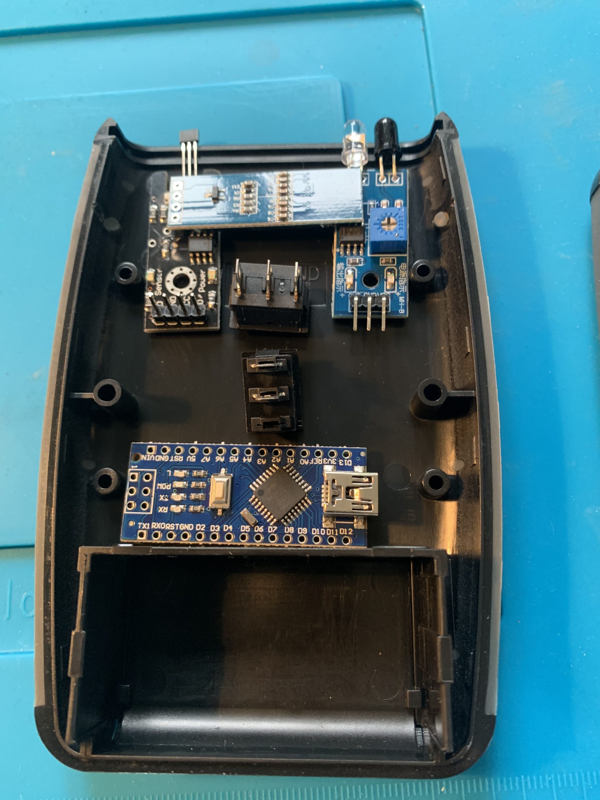
That got me thinking. I could i) use a Nano so I could box it in a smaller form-factor, ii) change the display for a little OLED for the same reason. Finally, iii) make it so I could use one of two sensors, depending on TT – so have a Hall effect sensor as well as the IR sensor just for good measure. (a tiny magnet, blu-tacked to the platter switches the sensor in this case).
I made a couple of changes to the original sketch to accomodate the different PINs on the Nano and the OLED display. I powered the Nano with a 9V PP3 (which you might know as a 1604x) since the Nano has a Vin and on-board regulator that can handle up to 12Vs. Given the device would only be used for a minute or so at a time, I wasn’t too concerned about power consumption.
It worked out pretty OK – in that it worked.
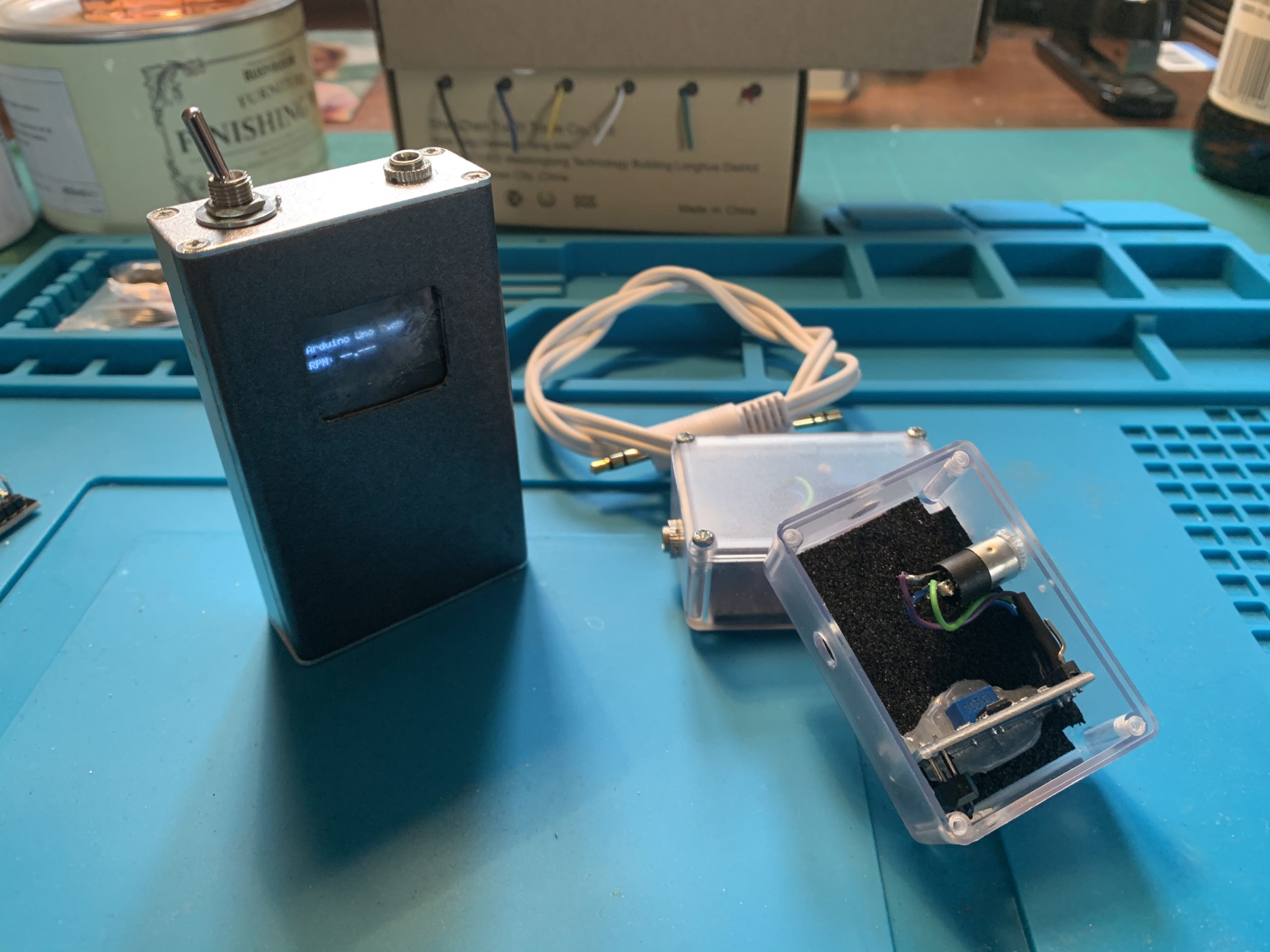
I housed it in a little metal project box. Frankly, a too small project box really, it was a bit of a messy cram. I had a small issue cutting the screen opening (originally I did it for a 128×64 OLED, but actually used a 128×32 one) and stupidly glued the screen and PET/perspex screen ‘cover’ I used from recycling some packaging by using – Superglue.
End result was the glue reacted with the PET or Perspex and it ended up cloudy.
Usable – but ugly.
The best bit was the off-board sensors, boxed in little cases, connected by a cable with 2.5mm plugs.
The ‘final’ iteration
It struck me that I could house the ‘works’ in a slightly bigger enclosure, include the different types of sensor, which could be switched between them and still have it ‘handheld’.
So, the bill of materials was as follows:
Enclosure, Arduino Nano, SPST on/off mini rocker switch, mini rocker (on-off-on), IR sensor, Hall effect sensor, OLED screen, NeoDymium Magnet
The on-off-on will switch the sensor signal to the Arduino. Rock left, and the left sensor is activated (The reflective sensor in my case). Rock right and the right sensor is activated. They are obviously never both active at the same time. (If you chose to do this, just remember the switch pins will likely be opposed – use a continuity check if in doubt!).
(I initially shared the signal wire and switched the 5V supply. The Hall effect sensor was fine with this but the IR sensor didn’t like it at all. Not sure why, possibly to do with the fact the signal cable is pulled high and the program measures HIGH to LOW transitions – but essentially above my technical pay grade). Wiring it the way I have done has the disadvantage that you are powering both sensors all of the time but my ‘on’ time is always less than a couple of minutes, so no real issue)
They will share the same signal (and ground) cable.
A rough layout of the components helps work out connector lengths etc.
The software firmware/sketch includes a provision to calibrate the actual value seen from the output of the crystal rather than assuming the ‘spec value’. I’d not done this on previous iterations – basically because I didn’t have a frequency counter. But now I do, so…. worth a quick check…
….. and at 15,630.60 Hz it was adrift from the theoretical 15,625 by about … 0.04% – so not too significant but worth dong if you can.
(Said another way, instead of reading 33.333 as you see in the picture, the uncalibrated sketch would have calculated 33.321)
While I modified the sketch for the OLED display from the original PCF8574 LCD library and otherwise hacked about with it by commenting out pieces I didn’t need – If you are minded to make one and are looking for the sketch, I later found somebody else had done something very similar but with tidier code so you’re better off going here for it.
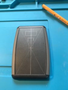
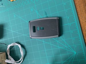
Marked out on the enclosure the display and switches and then used the old, time consuming, ‘drill many holes and file’ approach to making good…


Pretty much got as good as I thought was possible by hand… fairly pleased….

Connected the connecting wires.. and that’s basically it.
The result
Per the initial picture, it works excellently…
The turntable now runs at 33 and 1/3 with 180g Vinyl and needle down (it runs slightly faster needle up no record on – 33.35).
The output is consistent irrespective of which sensor – IR reflective or Hall effect, is used. (To use the Hall effect, I blu-tacked a really small Neo-Dymium magnet to the platter side. For the IR reflective (obstacle) sensor, I taped a small 3M self adhesive reflective strip to the platter side.
